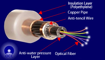
- Structure of light weight optical submarine cable
Technology Introduction
Optical Submarine Cable
There are basically two types of optical submarine cables. One is a light weight cable, and is used in deep sea areas of around 1,000m to 8,500m depth. The other is an armored cable being attached a steel wire to the light weight cable, and is used in a shallower area than about 1,000m depth.
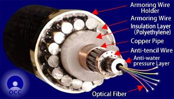
- Structure of single armored submarine cable
Optical Submarine Cable Laying Method
KCS is realizing the construction of cable laying with high quality and high reliability by performing the followings:
(1)Designs the most suitable speed of the cable payout and the ship, considering the water depth along with the cable laying route, ups and downs of the seabed and the types of the laying cables.
(2)Operates the cable handling facilities such as the cable engines or the ship's navigation system precisely according to the design.
Optical Submarine Cable Laying Procedure
Towards the cable landing station A, one end of the cable is paid out by the cable ship and landed. During this phase, the balloon buoys are attached along the cable to prevent possible damages to the cable.
Finally, the buoys are detached, allowing the cable to sink to the seabed.
The ship lays the cable towards the opposite station B or the designated point in mid-ocean.
At the designated point, the ship connects the cable with the end point of the previously laid cable from the station B.
After the final splice, the cable is released on the seabed.
Optical Submarine Cable Burial Method
In the water area shallower than the depth of 1,000 meters, cables are buried under the seabed mainly by two ways in order to protect them from damages, which might be caused by fishing activities or anchors of large vessels.
The one is to use the towed type burying machine, PLOW-II, which performs the simultaneous operation of cable laying and burial.
PLOW-II makes the installation period shorter because of the simultaneous operation of cable laying and burial, and is suitable for new and long distance operations.
Since PLOW-II is towed by the vessel on the seabed after threading the cable through it, it cannot be used for the burial operation after laying(burial after laying).
The working area of PLOW-II is limited depending on the seabed form or the slope.
The other is burial by ROV(MARCAS-IV, MARCAS-V).
ROV digs, by blasting waterjet into the seabed, a trench with the targeted burial depth by coming and going several times at the same section, and drops the cable into the trench. Because of this method, the construction efficiency of ROV is not better than PLOW-II. However,
ROV has the capability that it can float and move around on the sea bed, and ROV can work for the carved cable section which was caused by the final bight release, or in the area where PLOW-II can not be operated due to severe condition of the seabed.
Example of Cable Searching and Burial after Laying by ROV
Launching ROV and Localizing Failure Point
The cable ship arrives at the cable failure point which is estimated by the electrical and optical measurement from the cable landing station in advance.
The ship launches ROV onto the seabed. The precise cable failure location is specified by using the subsea cameras and cable sensors system of ROV.
Cable Cutting and Cable Recovery
ROV cuts the cable failure section by the manipulator and cutting tool.
It attaches the cable holding tool(gripper) to either cable end. After connecting the gripper with the rope paid out from the ship by the manipulator, the cable is recovered onto the ship. The transponder is installed around the other cable end,
and ROV is recovered onto the ship.
Buoy Installation, Cable Search and Recovery
The buoy is attached to the cable on the ship, and is released once on the sea.
Again, ROV is launched on the seabed, and searches the cable's other end relying on the transponder previously installed. By the same procedure as above item 2, the cable is recovered on the ship.
Insertion of Spare Cable and Cable Jointing
The recovered cable in above item 3 and the spare cable in the ship are jointed.
After the jointing, the ship approaches to the buoy in the item 3 laying the spare cable, and recovers the buoy and cable. After jointing the laying spare cable and the recovered cable,
the cables are released to the seabed.
Cable Burial after Laying
The attached spare cable and the exposed cable on the seabed due to the repair work are buried under the seabed by the waterjet of ROV.
Optical Submarine Cable Repair Method
There is a case in which an optical fiber cable is cut or damaged due to ocean earthquakes and fishing gears etc..
In the situation, the cable ship is urgently dispatched to the cable failure site and repairs the cable.
The cable repair procedure normally consists of the followings:
1) Localization of the cable failure point.
2) Recovery of the failure cable onto the ship
3) Cutting and removal of the cable failure section
4) Jointing of the recovered cable and the spare cable in the cable tank of the ship
5) Confirmation test and reburial of the cable
Optical Submarine Cable Repair Procedure
The distance of the cable failure location from the landing station is estimated by several tests in advance. The cable ship is navigated to the location by DGPS. At the place,
the tool for cable search and cutting, which is attached to the rope end, is paid out to the sea. By dragging the grapnel tool on the seabed, the cable is cut.
The rope with the grapnel at its end is paid out from the ship, and one end of the cut cable is caught by the grapnel(Cable Catch),
and is recovered to the ship(Cable Recovery). It might take more than one day to recover the cable from the sea of 8,000m depth. The optical fiber test and electrical test of its power feed conductor is carried out.
If there is still a failure, the cable is recovered further, the failure section is cut and removed.
At the end of the cable from which the failure section is removed, the waterproof treatment is carried out. After the attachment of the mooring rope and buoy to it, the cable is once dropped in the sea.
The cable ship moves for searching the other end of the cable, and repeats the same procedure as above item 2.
The optical fiber test and electrical test of its power feed conductor on the recovered cable is carried out in the same way as above item 2.
If there is a failure, the failure section is cut and removed. The cable is jointed with the spare cable which is stored in the cable tank(normally, Universal Joint technology is used).
The cable ship approaches to the previously installed buoy together with paying out the spare cable.
Holding the spare cable, the cable ship recovers the cable attached to the buoy again,
and joints it with the opposite end of the spare cable. For the final confirmation, the test is held between two cable landing stations of the cable.
After the confirmation of the communication normality, the on-board cable is released to the seabed, and the repair work is completed.